



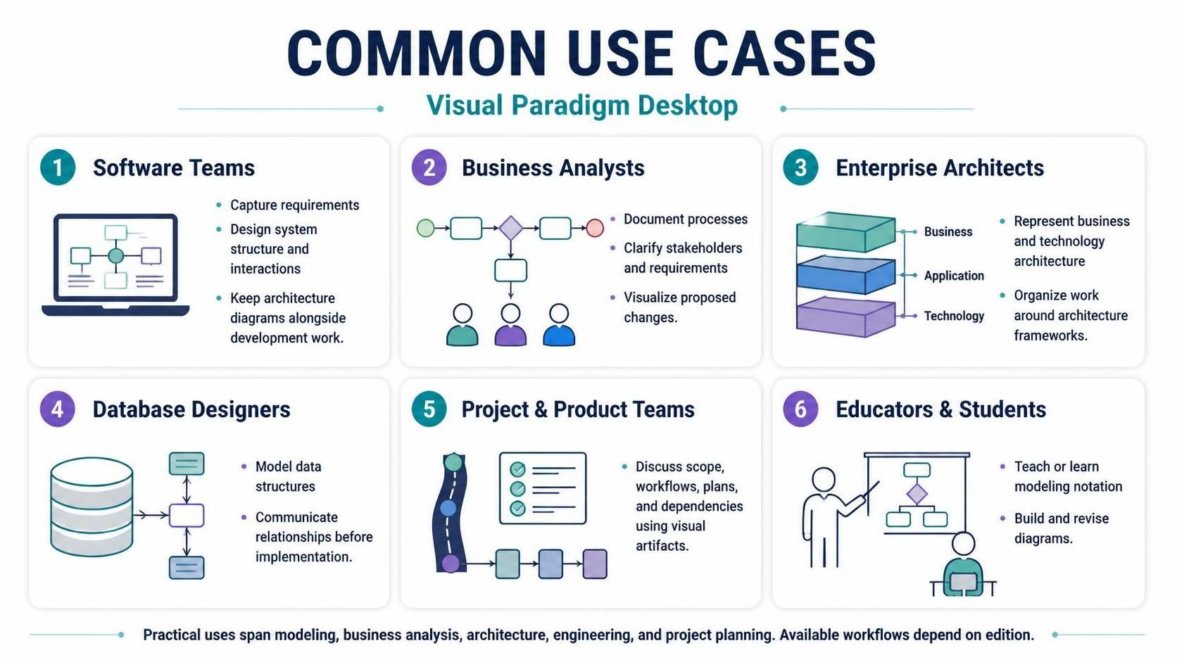
In the complex landscape of software development and enterprise planning, clarity is the most valuable asset. Visual Paradigm Desktop serves as a robust solution for bridging the gap between abstract requirements and concrete implementation. Whether you are designing a database schema, planning a business process, or mapping out an enterprise’s technology stack, this tool provides a unified environment to visualize, specify, construct, and document your systems.
This tutorial explores the core use cases of Visual Paradigm Desktop, guiding you through the methodologies used by Software Teams, Business Analysts, Enterprise Architects, and Database Designers to transform ideas into structured blueprints.
1. Software Teams: The Architecture of Interaction
For software development teams, the challenge lies in aligning user needs with technical implementation. Visual Paradigm facilitates a transition from high-level requirements to detailed code structure through a layered modeling approach.
The Modeling Hierarchy
A robust system design is rarely built on a single diagram. Instead, teams construct a narrative using specific diagram types:
- Use Case Diagrams: These act as the foundation, capturing the who and what of the system. They map out user roles and system goals, ensuring that the software solves actual user problems before a single line of code is written.
- Sequence Diagrams: Once the requirements are set, these diagrams illustrate the how. They detail the temporal order of interactions between objects or components, crucial for understanding complex workflows.
- Class Diagrams: These provide the structural backbone, describing domain concepts and their relationships (inheritance, association, aggregation).
- Component and Deployment Diagrams: These finalize the design by defining system modules and mapping them to the physical or virtual runtime environment.
Practical Example: In designing a reservation system, a team might start by defining the “Book Service” use case. They would then visualize the sequence of the request moving from the User Interface to the Reservation Service and finally to the Database. The Class Diagram would subsequently define the relationships between the Customer, Reservation, and ServiceItem entities.
2. Business Analysts: Visualizing the Flow of Value
Business Analysts (BAs) utilize Visual Paradigm to document and optimize the operational heartbeat of an organization. The primary tool for this is BPMN (Business Process Model and Notation), which standardizes the representation of business logic.
Key BPMN Elements
- Swimlanes: Essential for accountability. Swimlanes visually separate tasks by role (e.g., Employee, Manager, HR), clarifying who is responsible for each step.
- Gateways: These represent decision points or conditions within a flow, dictating which path a process should take based on specific data.
- Events: These mark the lifecycle of a process, indicating triggers (start), waiting periods, or terminations.
Pro Tip: Avoid the “Happy Path” trap. When modeling a leave approval process, ensure you explicitly map out exception paths (e.g., “Application Rejected” or “Missing Documents”). A complete model must account for failure states to be effective.
3. Enterprise Architects: The Strategic Blueprint
Enterprise Architects (EAs) view the organization from a macro perspective. They must ensure that business capabilities are supported by appropriate applications and technology infrastructure.
Frameworks and Methodologies
Visual Paradigm supports industry-standard frameworks like ArchiMate and TOGAF.
- ArchiMate: Allows architects to model the relationship between the Business Layer (capabilities), Application Layer (services), and Technology Layer (infrastructure).
- TOGAF ADM: Provides a structured phase model to organize the architecture development lifecycle.
Effective EA modeling avoids “diagram sprawl.” Instead of cluttering a single view with every detail, diagrams should be designed around specific communication goals, such as demonstrating how a specific business capability is supported by a specific application service.
4. Database Designers: From Concept to Code
Data is the backbone of any application, and Visual Paradigm empowers database designers to manage this asset from conceptual modeling to physical implementation.
The Engineering Workflow
- Conceptual Modeling: Designers use ERD (Entity Relationship Diagrams) to define entities (e.g., Student, Course) and their cardinality relationships.
- Logical Refinement: Attributes are added to entities to ensure data integrity (e.g., adding “Enrollment Date” to the “Enrollment” entity).
- Physical Implementation: The tool leverages Forward Engineering to generate SQL scripts for database creation and Reverse Engineering to import existing database structures back into the model for documentation or analysis.
5. Project & Product Teams: Documentation and Collaboration
Beyond technical modeling, Visual Paradigm functions as a collaborative hub for project planning. Diagrams serve as the universal language for scope definition, workflow visualization, and dependency mapping.
The tool integrates with project management workflows, allowing teams to generate comprehensive documentation, publish diagrams for stakeholder review, and track changes via version control. This ensures that the documentation remains synchronized with the evolving project scope.
6. Educators & Students: Learning the Art of Modeling
For academic settings, Visual Paradigm is an excellent pedagogical tool. It allows students to visualize abstract concepts and iterate on their designs. The ability to teach notation standards and then immediately apply them in a realistic environment accelerates the learning curve.
Best Practices: A Reusable Modeling Workflow
Regardless of your role, a successful modeling session follows a disciplined workflow:
- Define the Question: Start with a clear objective. Are you asking, “What are the main components?” or “Where does the process wait?”
- Select the Tool: Choose the diagram type that fits the question (e.g., Class Diagram for structure, BPMN for flow).
- Sketch the Concept: Draft a simplified version focusing on key elements and relationships. Avoid over-engineering the initial layout.
- Validate Semantics: Ensure symbols are used correctly according to UML or BPMN standards. Have domain experts review the model.
- Iterate and Maintain: Treat models as living documents. Update them as requirements change to maintain a single source of truth.