



In modern software engineering, the gap between design and documentation is often filled with friction. Teams model their systems in powerful desktop tools like Visual Paradigm, only to find that the resulting documentation is static, outdated, or difficult for stakeholders to access. This tutorial bridges that gap, explaining how to leverage the Visual Paradigm Pipeline to integrate Use Case Diagrams directly into OpenDocs.
We will walk through the architecture of a Hotel Room Booking System, demonstrating how to define actors, map functional requirements, and utilize advanced relationships like <<include>> to create a living, synchronized documentation workflow.
1. Understanding the Use Case Model Architecture
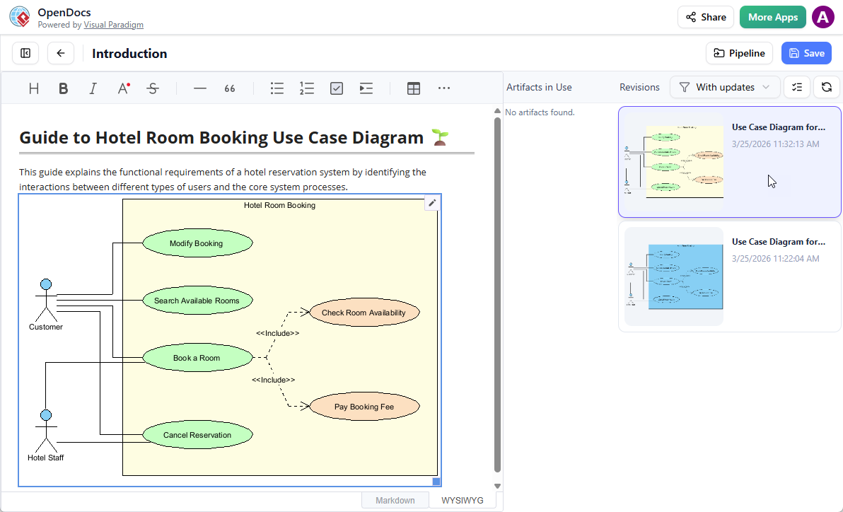
A Use Case Diagram is not merely a drawing; it is a structural blueprint of the system’s functionality from the user’s perspective. It identifies actors (users or external systems) and use cases (actions the system performs).
The Hotel Room Booking System
Let’s analyze the core entities involved in our sample system:
- Customer: The primary user who initiates the booking process.
- Hotel Staff: An administrative actor capable of managing reservations and modifications.
- Hotel Room Booking System: The boundary containing all internal processes.
By clearly defining these boundaries, we ensure that the subsequent documentation generated in OpenDocs remains accurate to the system’s scope.
2. Mapping Functional Requirements and Relationships
Once the actors are defined, we map the specific functions. In the provided architecture, we observe three distinct interactions for the Customer and one for the Staff.
- Modify Booking: An action allowing changes to an existing reservation.
- Search Available Rooms: A query function to check inventory.
- Book a Room: The primary transactional use case.
- Cancel Reservation: A reversal action managed by staff.
Advanced Modeling: The <<include>> Relationship
A critical concept in this diagram is the Include relationship (represented by a dashed arrow with the stereotype <<include>>). This indicates that a specific use case must happen as part of another use case.
In our example:
- The Book a Room process does not exist in isolation. It includes Check Room Availability and Pay Booking Fee.
- By using
<<include>>, we avoid redundancy. If we needed to change the logic for “Pay Booking Fee,” we would update it in one place, and it would reflect in every scenario that includes it.
3. The “Concept-to-Docs” Workflow
The true power of this architecture lies in the synchronization between the modeling tool and the documentation platform. Here is the step-by-step technical workflow:
Step 1: Modeling in Desktop
Begin by creating the diagram in Visual Paradigm Desktop. Ensure that the diagram is clean, uses standard UML notation, and clearly labels the <<include>> relationships. This serves as the “Single Source of Truth.”
Step 2: Pipeline Synchronization
When ready to document, the “Pipeline” feature acts as the transport mechanism. It captures the diagram artifact and pushes it to the OpenDocs repository. This is not a static image export (like a JPG); it is a structured artifact transfer.
Step 3: Integration in OpenDocs
Upon arrival in OpenDocs, the diagram is embedded directly into the documentation page. As shown in the interface, the diagram remains editable. This allows technical writers or stakeholders to annotate the diagram without leaving the documentation context. The system automatically handles version control, ensuring that if the diagram is updated in Desktop, the OpenDocs version can be refreshed to reflect the latest state.
4. Benefits of the Integrated Architecture
Adopting this workflow transforms how teams handle technical debt. By linking the modeling environment directly to the documentation platform, you achieve the following:
- Real-time Accuracy: Stakeholders always see the current version of the system logic.
- Reduced Overhead: No manual screenshots or copy-pasting required.
- Collaborative Review: The “Artifacts in Use” panel in OpenDocs allows teams to review the diagram’s revision history directly within the documentation interface.
By understanding the structural elements of the Use Case diagram and leveraging the pipeline integration, teams can ensure that their documentation evolves alongside their systems, maintaining a high standard of technical communication.