



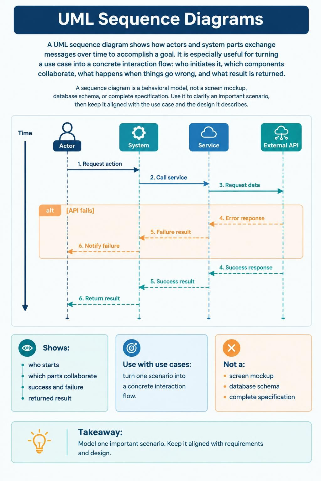
UML Sequence Diagrams are the bridge between high-level requirements and low-level technical implementation. They provide a dynamic view of a system, illustrating how objects and actors interact over time to achieve a specific goal. Unlike static diagrams that show structure, sequence diagrams tell a story: who initiates an action, which components collaborate, and how the system handles both success and failure.
In this tutorial, we will deconstruct the anatomy of a sequence diagram, understand the critical difference between synchronous and asynchronous messaging, and learn how to model complex logic like error handling using the alt fragment. We will also explore how tools like Visual Paradigm and VPasCode can help you translate these visual models into executable code.
1. Anatomy of the Interaction
At the top of a sequence diagram, you will see a series of vertical lines known as lifelines. These represent the participants in the interaction. In our example, we have four distinct roles:
- Actor: The human user or external system initiating the request.
- System: The main application or controller handling the request.
- Service: The internal logic or business layer processing the data.
- External API: A third-party resource the system depends on.
Time flows vertically from top to bottom. The horizontal arrows connecting these lifelines represent messages or method calls. The order of these arrows is crucial; it dictates the flow of execution.
2. Understanding Message Flow Types
Not all messages are created equal. Visual Paradigm and other modeling tools use specific arrow styles to denote how data is passed between components.
Synchronous Calls (Solid Arrow)
When the Actor sends a Request action to the System, this is a synchronous call. The sender waits for the receiver to complete the task and return a result before continuing. This is depicted by a solid line with a filled arrowhead.
Asynchronous Returns (Dashed Arrow)
When the System calls a Service, and that service eventually returns a Success response, the arrow is dashed. This indicates that the call was asynchronous or simply a return message (a response to the initial request). The sender does not necessarily block; it simply acknowledges the completion of the operation.
3. Modeling Logic with Alt Fragments
Real-world systems rarely follow a perfect linear path. Things break, APIs timeout, and validations fail. To model these scenarios, we use Combined Fragments. The most common is the alt (alternative) fragment.
In the diagram, notice the large orange box labeled alt with the condition [API fails]. This represents a conditional logic block. The diagram explicitly states: “If the API fails, execute the steps inside this box.”
Inside the alt frame:
- The External API returns an Error response.
- The Service processes this and returns a Failure result.
- The System notifies the Actor of the failure.
Outside the frame, the “else” path is implied: if the API does not fail, the system proceeds to return a success result.
4. From Model to Code: VPasCode Integration
Visual Paradigm’s VPasCode feature allows you to turn this visual model directly into code. Instead of manually writing the controller logic, you can export the sequence diagram to generate the skeleton code for your API endpoints and service classes.
Here is how the VPasCode logic for the interaction described above might look:
public class OrderController {

    @PostMapping("/request-action")
    public ResponseEntity handleRequest() {
        // 1. Actor requests action
        System.out.println("Requesting action...");

        try {
            // 2. Call service
            String result = orderService.processData();

            // 4. Success response path
            return ResponseEntity.ok(result);

        } catch (ApiException e) {
            // 3. Request data failed
            System.out.println("API failed");

            // 4. Error response path
            return ResponseEntity.status(500).body("Service Unavailable");
        }
    }
}5. Best Practices for Sequence Modeling
When creating your own sequence diagrams, keep these core principles in mind to ensure your diagrams remain effective communication tools rather than cluttered technical specifications.
- Focus on Scenarios: Do not try to diagram every single line of code. Focus on one important scenario (e.g., “Successful Login” or “Failed Payment”).
- Behavioral vs. Structural: Remember that a sequence diagram is a behavioral model. It does not show database schemas or screen layouts. It shows the flow.
- Alignment with Use Cases: Always keep your sequence diagram aligned with the Use Case it represents. If a Use Case describes “User Uploads File,” the sequence diagram must show the Actor, the System, and the necessary file storage services.
Summary: What Sequence Diagrams Are Not
It is equally important to understand what a sequence diagram is not. It is not a screen mockup, a database schema, or a complete specification of the system’s entire logic. It is a focused view designed to clarify the interaction flow between specific parts of the system.
By mastering these diagrams, you can effectively communicate complex system behaviors to developers, stakeholders, and AI-assisted coding tools, ensuring that the final software architecture is robust and aligned with user requirements.