



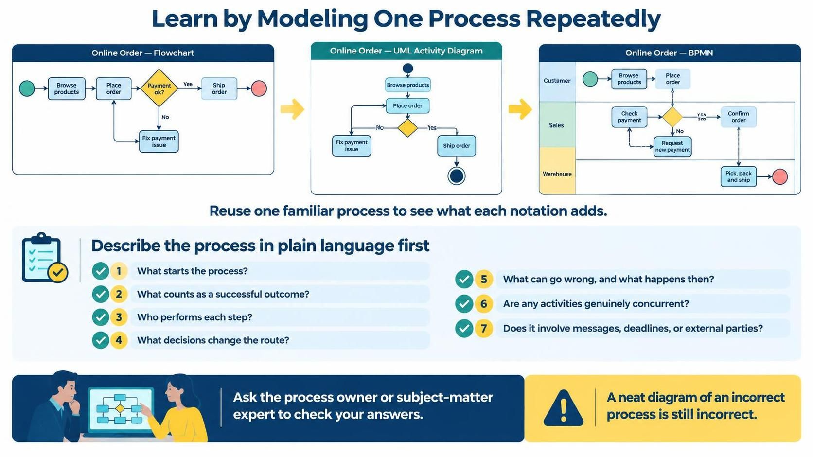
Effective business analysis and system design require more than just knowing how to draw shapes on a screen. The true power of modeling lies in the ability to refine a single, familiar concept into increasingly complex and executable representations. This tutorial explores the strategy of “Learning by Modeling One Process Repeatedly,” using the scenario of an Online Order to demonstrate the progressive evolution from a basic flowchart to a full BPMN execution model.
By utilizing the VPasCode ecosystem within Visual Paradigm, you can transition seamlessly between syntax styles, ensuring that your technical documentation remains accurate and your understanding deepens at every stage.
Phase 1: The Foundation – Describing in Plain Language
Before opening any modeling tool or writing a single line of syntax, the most critical step is to define the process logic in plain language. This ensures that the “what” and “why” are understood before the “how” is addressed.
For our Online Order scenario, we must define seven key components:
- Trigger: What initiates the process? (e.g., Customer clicks “Checkout”).
- Outcome: What defines a successful completion? (e.g., Order shipped and paid).
- Actors: Who performs the steps? (e.g., Customer, Sales System, Warehouse).
- Decisions: What conditions change the route? (e.g., Is payment approved?).
- Exceptions: What happens when things go wrong? (e.g., Payment fails).
- Concurrency: Are activities happening simultaneously?
- Interactions: Are there messages or external parties involved?
Phase 2: The Flowchart (Basic Logic)
The journey begins with a standard flowchart. This notation is perfect for understanding the high-level logic without worrying about complex constraints. It focuses on the sequence of steps and the decision points.
Modeling the Online Order (Flowchart)
In this phase, we map the linear flow of a customer browsing, ordering, and the subsequent payment check.
// VPasCode: Flowchart Syntax
// Scenario: Simple Online Order Flow

Start => [Browse Products]
[Browse Products] => [Place Order]
[Place Order] => {Payment Ok?}

{Payment Ok?} == Yes => [Ship Order]
{Payment Ok?} == No => [Fix Payment Issue]
[Fix Payment Issue] => [Place Order]

[Ship Order] => End
Key Takeaway: The flowchart gives you the “Skeleton.” It answers “What happens next?” but ignores “Who does it?” or “Where does it happen?”.
Phase 3: The UML Activity Diagram (System Logic)
Once the logic is established, we often move to a UML Activity Diagram. This notation adds the concept of a system state and concurrent flows. It is more formal than a flowchart and often used by software architects to define system behavior.
Refining with UML Activity
Here, we introduce the concept of a “System” boundary and ensure we handle the loop correctly.
// VPasCode: UML Activity Diagram Syntax

* => [Browse Products]
[Browse Products] => [Place Order]
[Place Order] => {Payment Check}

{Payment Check} == Yes => [Ship Order]
[Ship Order] => *

{Payment Check} == No => [Fix Payment Issue]
[Fix Payment Issue] => [Place Order]
Key Takeaway: The UML diagram is the “Muscle.” It adds the control flow logic required for software implementation but still lacks the organizational context.
Phase 4: BPMN (Business Process Model and Notation)
The final and most advanced layer is BPMN. This is the standard for business process modeling because it introduces Swimlanes (Actors) and specific event types (Start, End, Intermediate). It distinguishes between what a human does and what a system does.
The Complete BPMN Model
Using VPasCode, we can now define the specific lanes (Customer, Sales, Warehouse) and the gateway logic required for the order to be executed.
// VPasCode: BPMN Syntax

// Define Lanes
lane "Customer" {
    startEvent "Customer Starts"
    activity "Browse Products"
    activity "Place Order"
}

lane "Sales" {
    activity "Check Payment"
    gateway "Is Payment Valid?"
    activity "Confirm Order"
}

lane "Warehouse" {
    activity "Pick, Pack, and Ship"
}

// Define Flows
"Customer Starts" -> "Browse Products"
"Browse Products" -> "Place Order"
"Place Order" -> "Check Payment"
"Check Payment" -> "Is Payment Valid?"

"Is Payment Valid?" == Yes -> "Confirm Order"
"Is Payment Valid?" == No -> "Fix Payment Issue"

"Confirm Order" -> "Pick, Pack, and Ship"
"Pick, Pack, and Ship" -> endEvent "Order Shipped"
Key Takeaway: BPMN is the “Brain and Nervous System.” It adds the organizational context (Swimlanes), the specific roles (Actors), and the strict rules of execution (Gateways and Events).
Summary of Progression
By reusing the Online Order example, we have demonstrated the value of progressive modeling:
- Flowchart: Defined the logical sequence and decision points.
- UML Activity: Formalized the control flow and system state.
- BPMN: Added organizational structure, roles, and execution semantics.
Using VPasCode allows you to write these diagrams in code, making version control, sharing, and consistency across your team effortless. Whether you are a business analyst or a software architect, mastering this progression ensures your diagrams are not just pictures, but accurate representations of reality.