



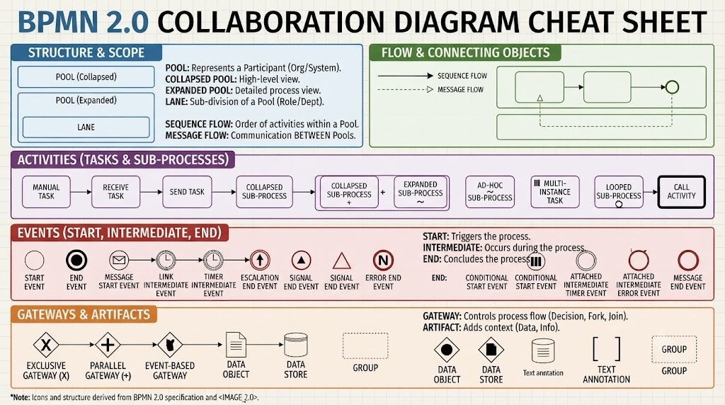
Welcome to your comprehensive guide on Business Process Model and Notation (BPMN) 2.0. If you are a business analyst, process architect, or developer, you have likely encountered the complexity of translating a business requirement into a technical blueprint. This tutorial focuses on the Collaboration Diagram—the most critical structure for modeling interactions between different systems, organizations, or departments.
Using the power of Visual Paradigm combined with its AI ecosystem, we will deconstruct the “Cheat Sheet” of BPMN elements shown in the reference material. We will move beyond simple drawing and look at the architectural logic that governs how information flows across boundaries.
Section 1: The Foundation – Structure and Scope
Before drawing a single activity, you must define the “Stage” where your play unfolds. In BPMN, this is defined by the concept of a Pool.
Understanding the Pool
A Pool represents a Participant. This could be a company, a department, or a specific IT system. It acts as a container for all the processes associated with that entity. Visual Paradigm makes it easy to toggle between two distinct views:
- Collapsed Pool: This is your high-level view. It shows a single box labeled with the entity’s name. Use this when you are presenting to stakeholders who only need to see the “big picture” without getting bogged down in details.
- Expanded Pool: This reveals the internal complexity. Once expanded, the pool becomes a container for Lanes.
Defining Lanes
Think of a Lane as a sub-division of a Pool. It represents a specific role, department, or responsibility within the broader entity.
Example: In a “Customer Service” Pool, you might have Lanes for “Sales,” “Support,” and “Billing.”
Inside these pools and lanes, you will utilize two primary types of flows:
- Sequence Flow: This is the order of activities within a pool (or lane). It dictates the chronological progression of the process.
- Message Flow: This is the communication between pools. It represents a message, document, or data packet sent from one entity to another.
Section 2: The Actors – Activities and Tasks
Once the structure is set, the “actors” enter the stage. These are the Activities. BPMN 2.0 is incredibly granular, allowing you to specify exactly who is doing what.
Standard Tasks
Visual Paradigm supports a vast library of task types to ensure precision:
- Manual Task: An activity performed by a human without the aid of a computer system.
- User Task: A task performed by a human using a computer system (the most common task type).
- Service Task: A task performed by an automated system (e.g., an API call to a payment gateway).
- Script Task: A task performed by a script (e.g., a Python or SQL script running in the background).
Sub-Processes and Call Activities
Complex processes often contain smaller, self-contained processes. BPMN handles this elegantly:
- Collapsed Sub-Process: Looks like a simple task but contains hidden logic. It represents a process that is defined elsewhere in the diagram.
- Expanded Sub-Process: Unfolds to show the internal sequence of events, tasks, and gateways.
- Call Activity: A specific way to reference a global sub-process (a reusable process defined in a separate file or diagram) from within a main process.
Section 3: The Timing – Events
Events are the “heartbeats” of your diagram. They are represented by circles and mark the beginning, middle, or end of a process.
Start, Intermediate, and End
- Start Event: The trigger. It initiates the process (e.g., “Order Received”).
- Intermediate Event: Something that happens during the process. This is where the magic of BPMN lies. You can have intermediate events that pause the flow until a timer expires, a message arrives, or a signal is detected.
- End Event: The conclusion. It signifies that the process has finished successfully or been terminated.
Event Types
The reference diagram highlights the importance of specific triggers:
- Timer Events: Used for delays or deadlines (e.g., “Wait 3 days”).
- Message Events: Used when waiting for communication from another participant.
- Signal Events: Used to broadcast a signal that multiple processes can listen for.
Section 4: The Decision Makers – Gateways and Artifacts
If events are the heartbeats and tasks are the muscles, Gateways are the brain. They control the flow of the process based on logic.
Gateways
Gateways determine how the process branches or merges:
- Exclusive Gateway (X): The classic “If/Else” logic. It chooses one path out of many based on a condition (e.g., “Is credit approved? Yes -> Ship, No -> Cancel”).
- Parallel Gateway (+): The “Fork and Join.” It splits the flow into multiple simultaneous paths (e.g., Send email AND update inventory).
- Event-Based Gateway: A unique gateway that waits for one of several possible events to occur first.
Artifacts
Not everything in a diagram is an action. Artifacts add context:
- Data Object: Represents a piece of information (like a form or document) being used.
- Data Store: A repository where data is permanently stored (like a database).
- Group: A visual box used to group elements together for documentation purposes without affecting the process logic.
Conclusion
Mastering BPMN 2.0 is not just about memorizing shapes; it is about understanding the flow of information and responsibility. By utilizing Visual Paradigm’s robust toolkit, you can transform abstract business needs into precise, executable models. Whether you are designing a simple workflow or a complex enterprise collaboration, these foundational elements provide the clarity needed for success.