



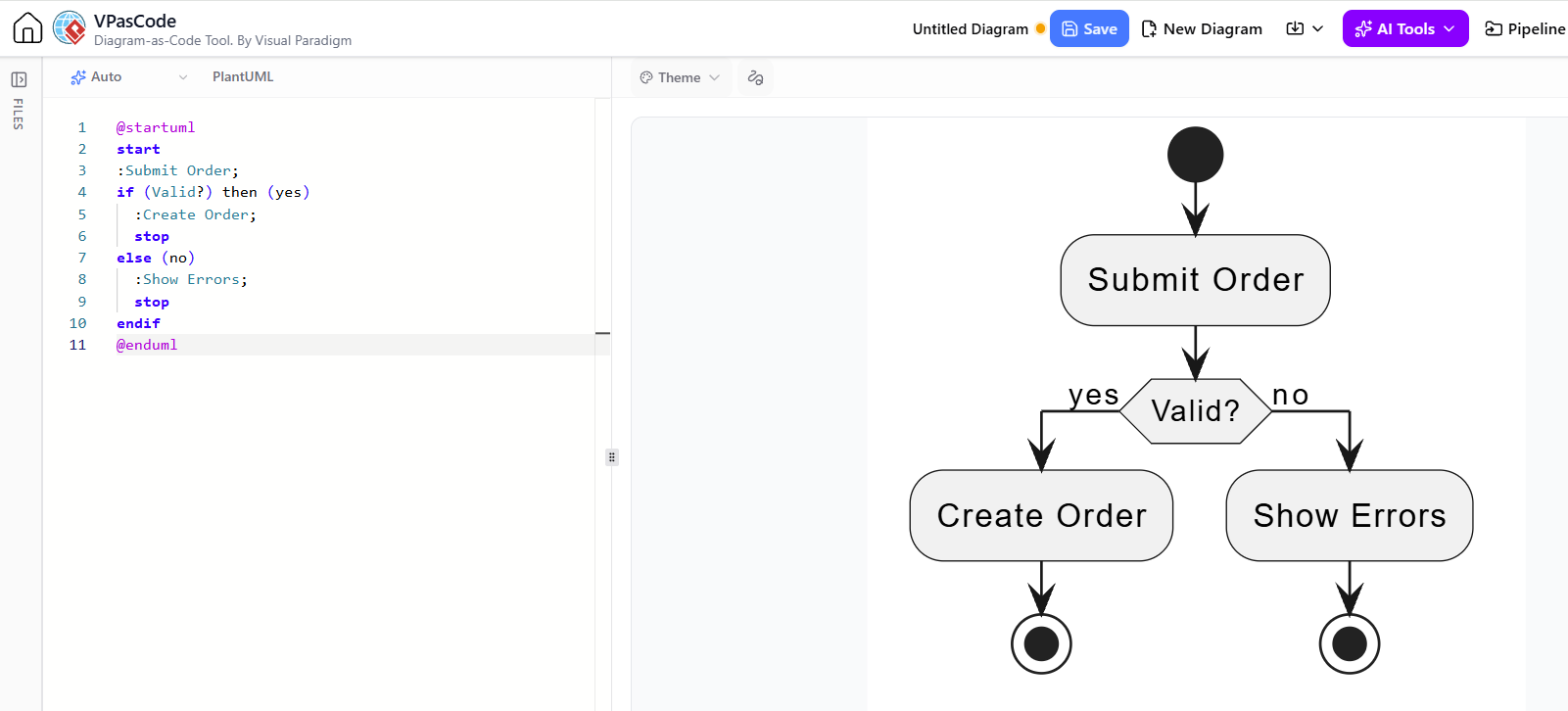
In the realm of software architecture and system design, the ability to visualize complex logic is paramount. Traditionally, this required dragging and dropping shapes on a canvas, a process that can be tedious and prone to formatting errors. However, modern tools like Visual Paradigm’s VPasCode have revolutionized this workflow by introducing “Diagram-as-Code” functionality. This tutorial explores how to use text-based modeling to generate a professional Activity Diagram, specifically focusing on the logic of an “Order Submission” process.
Understanding the VPasCode Workflow
VPasCode allows developers and architects to write code in a specific syntax (in this case, PlantUML) to automatically render diagrams. This approach offers several distinct advantages over manual drawing:
- Version Control Friendly: Since the diagram is text, it can be tracked in Git repositories alongside your source code.
- Rapid Prototyping: You can visualize a complex logic flow in seconds without worrying about alignment.
- Consistency: The tool ensures that all shapes, fonts, and connectors adhere to the selected theme automatically.
The interface typically splits the workspace into two distinct areas: the Editor on the left, where you write the logic, and the Previewer on the right, which renders the graphical representation in real-time.
Step-by-Step: Building the “Submit Order” Activity Diagram
Let us walk through the specific logic provided in the context: an order submission process that validates data before proceeding. This is a classic “Decision Node” pattern in Activity Diagrams.
1. The Header and Start Node
Every PlantUML diagram requires a specific header to define the diagram type. For activity diagrams, we use
@startuml</code>. The process begins with the <code>start</code> keyword, which renders as a solid black circle in the graphical view.</p>

<h3>2. Defining the Process Flow</h3>
<p>Once the process starts, the flow moves to an action node. In our scenario, the action is "Submit Order". In VPasCode syntax, actions are prefixed with a colon (<code>:</code>). The semicolon (<code>;</code>) acts as a terminator for the command, similar to many programming languages.</p>

<h3>3. Implementing Logic with Decision Nodes</h3>
<p>The core of this diagram is the validation check. In standard UML, this is represented by a diamond shape. In VPasCode, we use the <code>if</code> statement structure. This is powerful because it handles both the logic and the rendering of the decision diamond automatically.</p>

<p>The syntax structure is as follows:</p>
<ul>
    <li><code>if (Condition?)</code>: Defines the decision point.</li>
    <li><code>then (yes)</code>: The path taken if the condition is true.</li>
    <li><code>else (no)</code>: The path taken if the condition is false.</li>
</ul>

<h3>4. Branching Logic and Termination</h3>
<p>Inside the <code>if</code> block, we define what happens next.
<br><strong>Path A (Valid):</strong> If the order is valid, the system executes <code>:Create Order;</code> and then reaches a stop point.
<br><strong>Path B (Invalid):</strong> If the order is invalid (the <code>else</code> block), the system executes <code>:Show Errors;</code> and stops.</p>

<p>The <code>stop</code> keyword is crucial. It tells the renderer to end the current path. Finally, <code>endif</code> closes the conditional block, and <code>@enduml
terminates the entire diagram definition.
The Complete Code Snippet
Copy the following code directly into the VPasCode editor to replicate the “Submit Order” logic shown in the example:
@startuml
start
:Submit Order;
if (Valid?) then (yes)
  :Create Order;
  stop
else (no)
  :Show Errors;
  stop
endif
@enduml
When rendered, this code produces a clean, professional Activity Diagram. You will see a solid black circle (Start) leading to a rounded rectangle “Submit Order,” which flows into a hexagonal decision node labeled “Valid?”. From there, arrows labeled “yes” and “no” direct the flow to their respective action nodes, eventually terminating at black circles with outer rings (End Nodes).
Conclusion
By mastering the syntax of VPasCode, you shift your focus from “drawing” to “modeling.” Whether you are designing a simple validation check or a complex enterprise workflow, the text-based approach ensures your diagrams remain readable, editable, and perfectly synchronized with your architectural intent.